4-axis robot controller
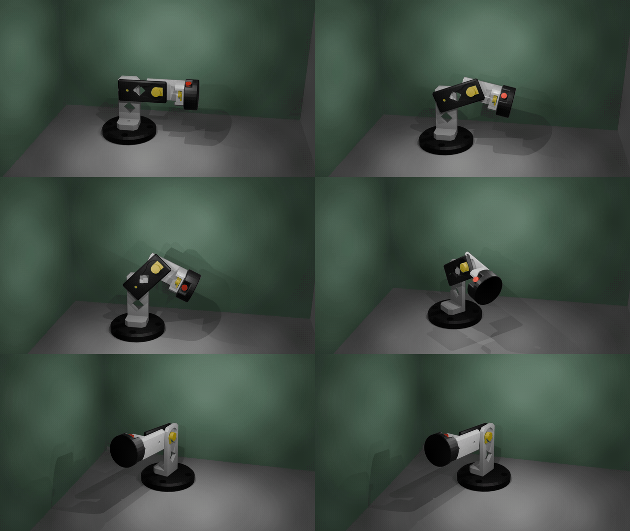
KB2040 4-Axis Robot Arm Controller
USB controller for a 4-axis robot arm using an Adafruit KB2040 (RP2040). Four potentiometers for axis control plus a button for gripper/trigger — all read over a simple serial protocol.
BOM
| Part | Qty | |
|---|---|---|
| Adafruit KB2040 | 1 | |
| 10kΩ linear potentiometer | 4 | WWZMDiB |
| Tactile push button (momentary) | 1 | US-SKU E429 |
| 3D-printed enclosure | 1 | |
| USB-C cable | 1 |
Wiring
| KB2040 | Connected to |
|---|---|
| A0 (GP26) | Pot 1 wiper |
| A1 (GP27) | Pot 2 wiper |
| A2 (GP28) | Pot 3 wiper |
| A3 (GP29) | Pot 4 wiper |
| Pin 9 (GP9) | Button (other leg → 3.3V) |
| 3.3V | Pot 1–4 left leg |
| GND | Pot 1–4 right leg, button pull-down |
Potentiometer legs: left → 3.3V, right → GND, wiper (center) → analog pin.
Button is active-high (press sends 3.3V to GP9). The firmware uses the RP2040's internal pulldown so no external resistor is needed.
Firmware
Uses the Earle Philhower RP2040 core. Target board: Adafruit KB2040.
arduino-cli compile --fqbn rp2040:rp2040:adafruit_kb2040 controller/arduino-cli upload --fqbn rp2040:rp2040:adafruit_kb2040 controller/Analog resolution: 12-bit (0–4095).
Serial protocol (115200 baud)
Send a single character, get CSV back:
| Cmd | Response | Example |
|---|---|---|
a | ch1,ch2,ch3,ch4 | 2048,1023,3072,0 |
b | button (0/1) | 0 |
p | press edges (0/1) | 1 |
r | release edges (0/1) | 0 |
s | button;ch1,ch2,ch3,ch4 | 0;2048,1023,3072,0 |
Display (optional)
Python tkinter GUI (display.py) shows live pot bars and button state. Requires pyserial.
pip install pyserialpython display.pySTLs
| File | Description |
|---|---|
CONTROLLER-BASE.stl | Enclosure base — holds KB2040, pots, and button |
CONTROLLER-ARM1.stl | Potentiometer knob — axis 1 |
CONTROLLER-ARM2.stl | Potentiometer knob — axis 2 |
CONTROLLER-ARM3.stl | Potentiometer knob — axis 3 |
CONTROLLER-ARM4.stl | Potentiometer knob — axis 4 |
CONTROLLER-CLUTCH.stl | Clutch/gripper button cap |
Designed in Blender — source file: CONTROLLER.blend
Notes
- Designed for the Earle Philhower RP2040 Arduino core
- Button uses INPUT_PULLDOWN — no external resistor required
- All four pots are read continuously; data is returned on request to avoid flooding the serial buffer